| HONOR |
|
The credit belongs to the past, the dream guide to the future,
The
pursuit of the first creed, motivate
us
Way forward, never stop.
We will be
This is a power,
bearing the past, create the future |
|
|
| PRODUCTS |
|
| Pneumatic cylinder series |
|
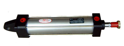
The QGA, QGB series cylinder
|
|
|
|
The QGA series No buffer cylinder
|
| |
|
| |
QGA series cylinder is unbuffered devices ordinary cylinder, the working medium for oily mist compressed air after purification. |
|
|
|
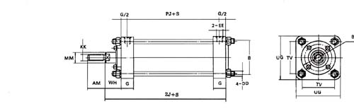
| Marking explanation:QGA①-②-③ |
| |
|
|
① Bores ② the cylinder stroke ③ cylinder installed unmarked forms: the basic type f: Flanged |
| |
F: After the flange type G: Tripod-B: middle pendulum shaft S: tail hanging |
| |
| Basic parameters: |
|
Bores
(mm)
|
Travel range
(mm)
|
Working pressure range
(MPa)
|
The ambient temperature
(℃)
|
Theoretical force (N) (A pressure of 0.4MPa when computing)
|
|
thrust
|
tension
|
|
φ40
|
0~300
|
0.15~0.8
|
-10~80
|
500
|
450
|
|
φ50
|
0~300
|
0.15~0.8
|
780
|
700
|
|
φ63
|
0~800
|
0.15~0.8
|
1250
|
1120
|
|
φ80
|
0~800
|
0.15~0.8
|
2010
|
1880
|
|
φ100
|
0~1500
|
0.15~0.8
|
3140
|
2950
|
|
φ125
|
0~2000
|
0.1~0.8
|
4910
|
4720
|
|
φ160
|
0~2500
|
0.1~0.8
|
8040
|
7720
|
|
φ200
|
0~2500
|
0.1~0.8
|
12570
|
12250
|
|
φ250
|
0~2500
|
0.1~0.8
|
19640
|
19140
|
|
| |
|
Note: According to the above table when the cylinder is chosen, should theoretical push and pull increases of 15 to 20%
|
|
|
|
|
|
|
QGB series buffer cylinder
|
| |
| |
|
| |
QGB50×180-CA
|
| |
| |
The cylinder of QGB series buffer cylinder. The working medium is an oily mist compressed air purification. |
| |
The buffering action of the cylinder, is a cushioning device mounted on the internal cylinder starts to work when the piston moves to close to the stroke end, so that |
| |
Reduce piston speed, smooth movement, to avoid the impact of the phenomenon, the series cylinder Bore φ40, φ50mm not adjustable slow |
| |
Chong, Bore φ63mm and above Bore cylinder adjustable cushioning. |
| |
|
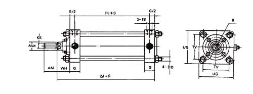
| Marking explanationQGA①-②-③ |
| |
| |
| |
①Bores ②Cylinder stroke ③Cylinder installed unmarked forms: basic type f: front flange type |
| |
|
F: After the flange type G: Tripod-B: middle pendulum shaft S: tail hanging |
| Basic parameters |
| |
| Note:According to the above table when the cylinder is chosen, the theoretical thrust and should be increased 15 to 20% Rally |
| |
|
Bores
(mm)
|
Travel range
(mm)
|
Working pressure range
(MPa)
|
The ambient temperature
(℃)
|
Theoretical force (N) (A pressure of 0.4MPa when computing)
|
|
thrust
|
tension
|
|
φ40
|
40~300
|
0.15~0.8
|
-10~80
|
500
|
450
|
|
φ50
|
40~300
|
0.15~0.8
|
780
|
700
|
|
φ63
|
63~800
|
0.15~0.8
|
1250
|
1120
|
|
φ80
|
63~800
|
0.15~0.8
|
2010
|
1880
|
|
φ100
|
100~1500
|
0.15~0.8
|
3140
|
2940
|
|
φ125
|
100~2000
|
0.1~0.8
|
4920
|
4520
|
|
φ160
|
160~2500
|
0.1~0.8
|
8040
|
7540
|
|
φ200
|
160~2500
|
0.1~0.8
|
12560
|
12060
|
|
φ250
|
250~2500
|
0.1~0.8
|
19640
|
18860
|
|
φ320
|
300~2500
|
0.1~0.8
|
32160
|
30910
|
|
φ400
|
300~2500
|
0.1~0.8
|
50400
|
48400
|
|
|
|
|
|
|
|
| Previous:Hydraulic cylinder series
Next:Hydraulic power unit series |   |
|
|